Almost there!

It’s been a long time since the last update!
Nothing happened with the computer for quite some time but eventually I found some time to work on it again.
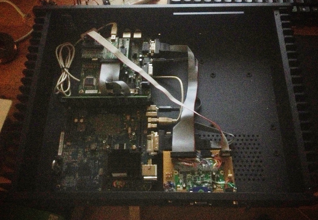
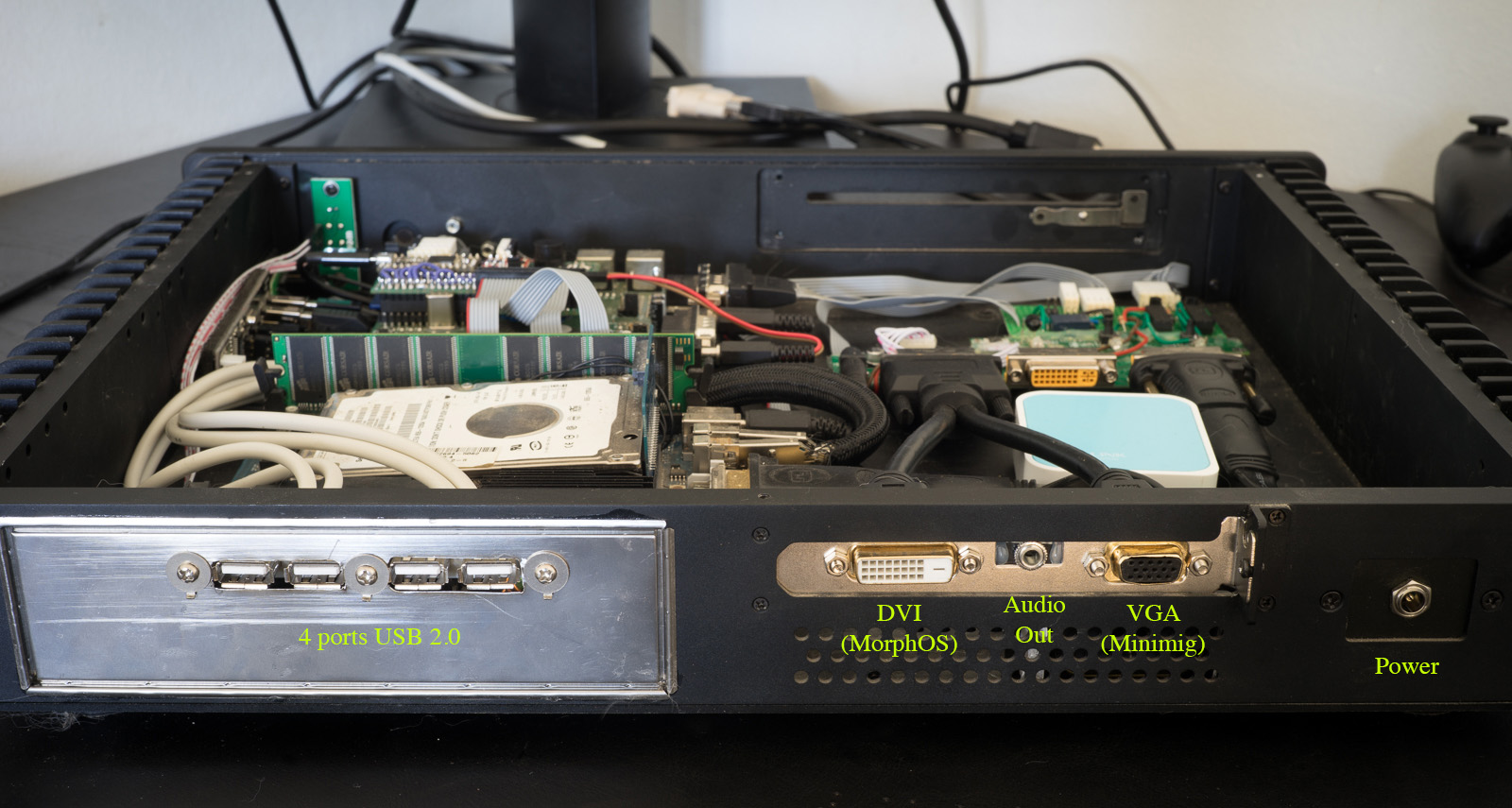
All that is really missing now is a dvd drive and possibly putting an ethernet jack on the back of the machine. It’s wifi-only at the moment, using an ethernet->wifi dongle.

DSC05133

DSC05116
DSC05121

Here is a video of it in action: https://youtu.be/x7fHtTq0tKo


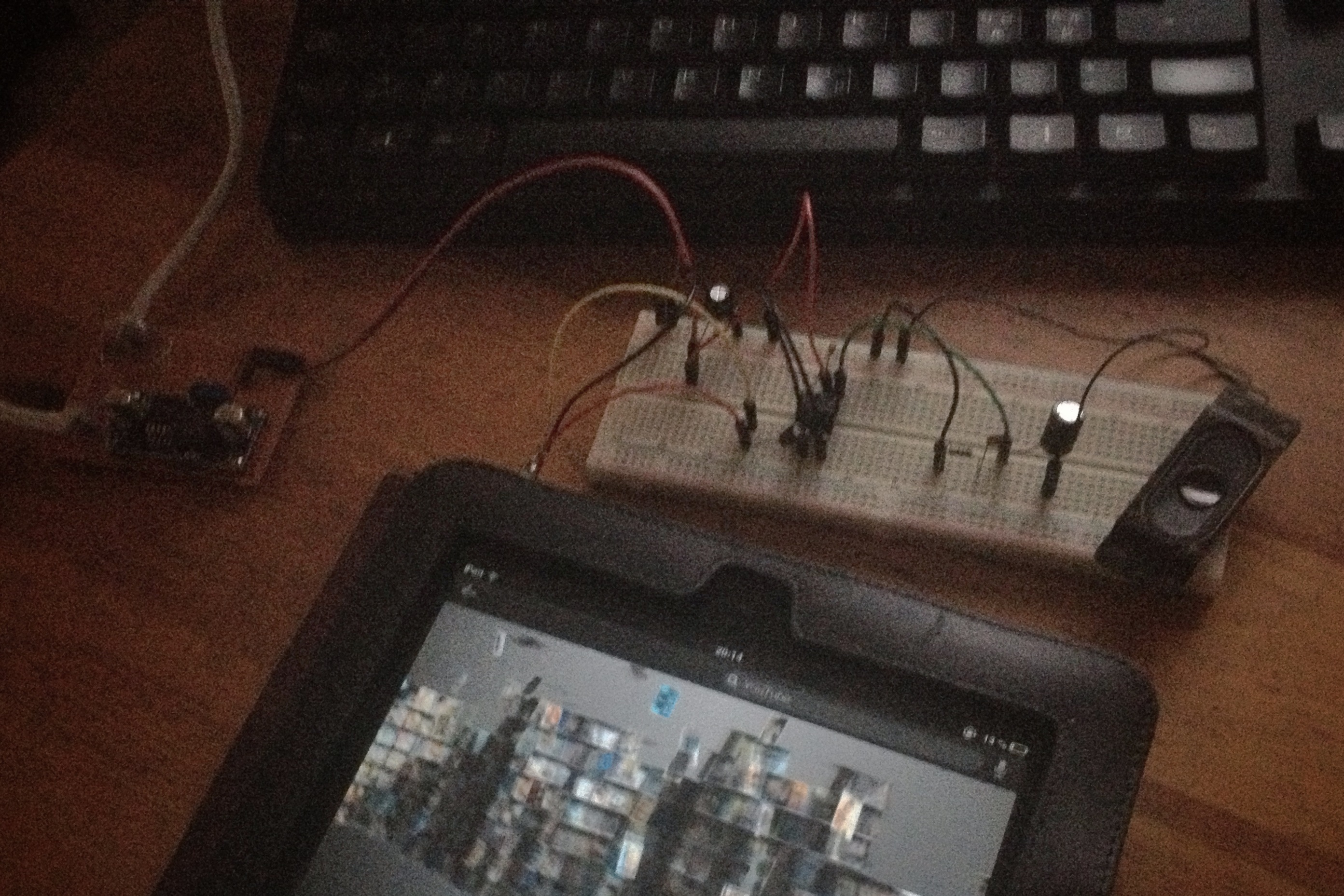
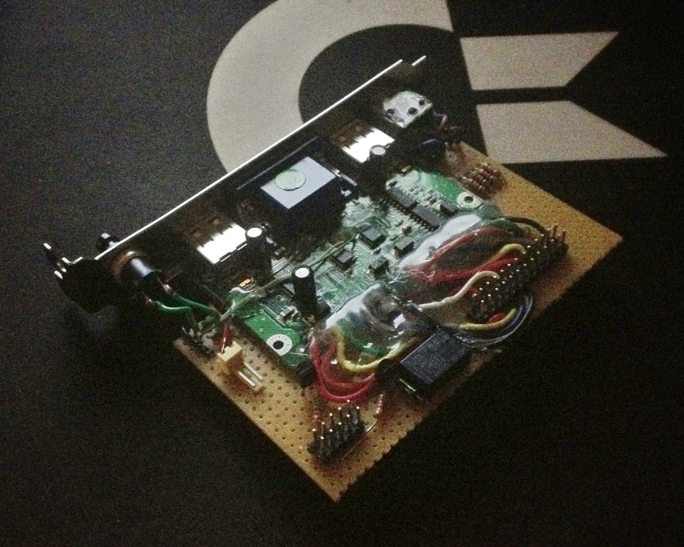
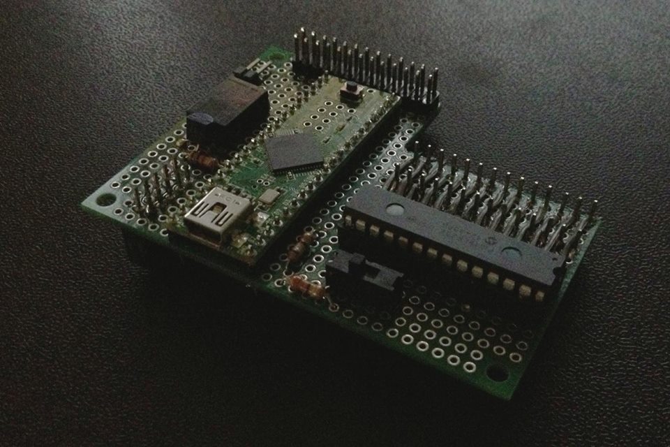
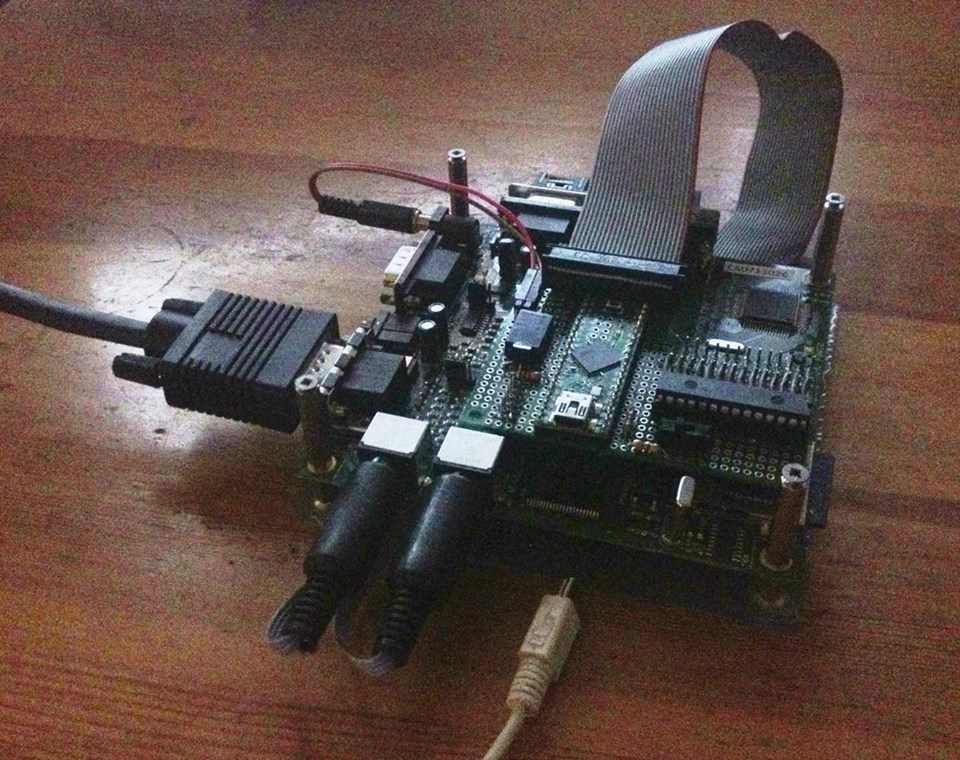
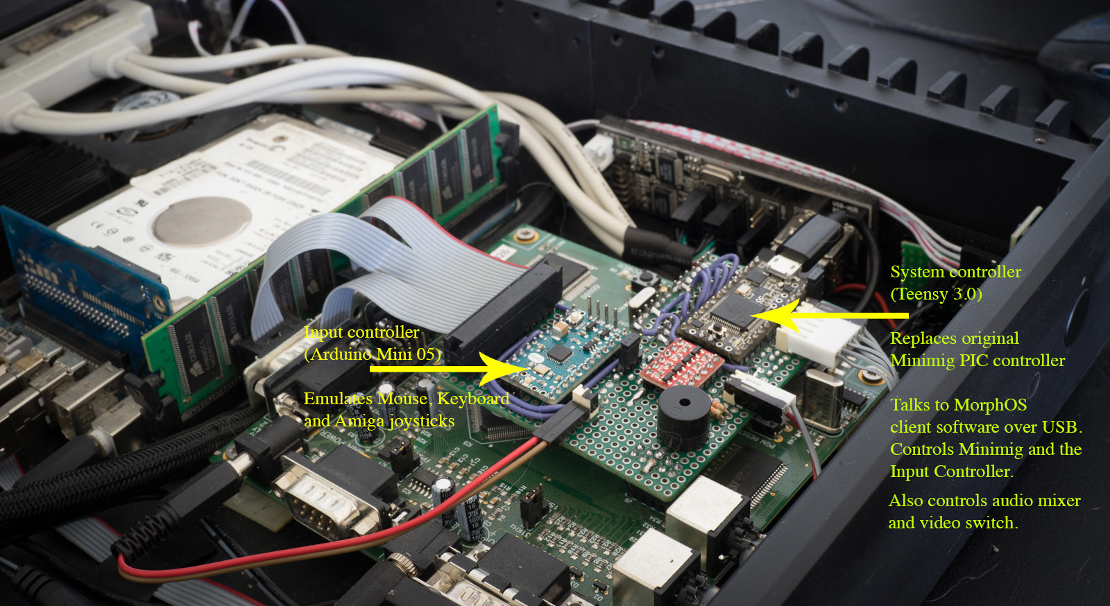
I redid the Minimig controller, removing the need for the original PIC controller. The main controller is now a Teensy 3.0.
This one was chosen because has 12Mbit/s bandwidth over USB – this is good enough for floppy disk transfer between MorphOS and the Minimig.
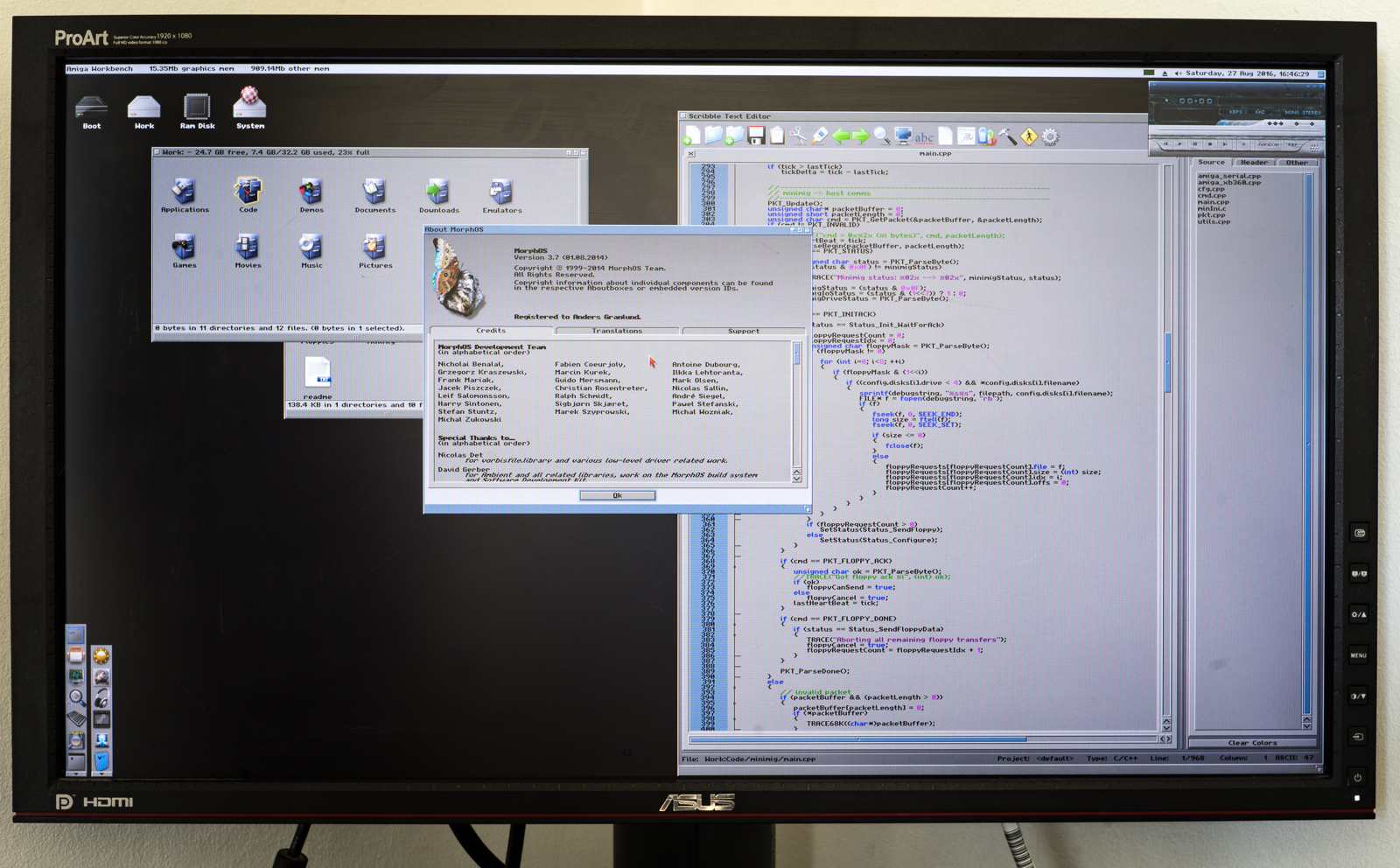
It has a custom firmware that allows the Minimig to be completely controlled from the client software running on MorphOS, including reading floppies, getting input, changing settings, and so on.
Multi disk games are automatically detected from the filename, and it is possible to override any setting on a per-game basis.
Mouse, Keyboard and gamepad input are forwarded from MorphOS to a second microcontroller, an Arduino Mini, which emulates a PS/2 Keyboard, Mouse and the Amiga joysticks.

There is no OSD like on the stock Minimig. Instead there are special key combinations to press for resetting, changing certain settings and so on.
An ini file is used for setting default settings and it is possible to override any of these on a per game basis.
Multi disk games are automatically detected by filename, and it’s again possible to specify disk settings in the ini file.
DSC05117

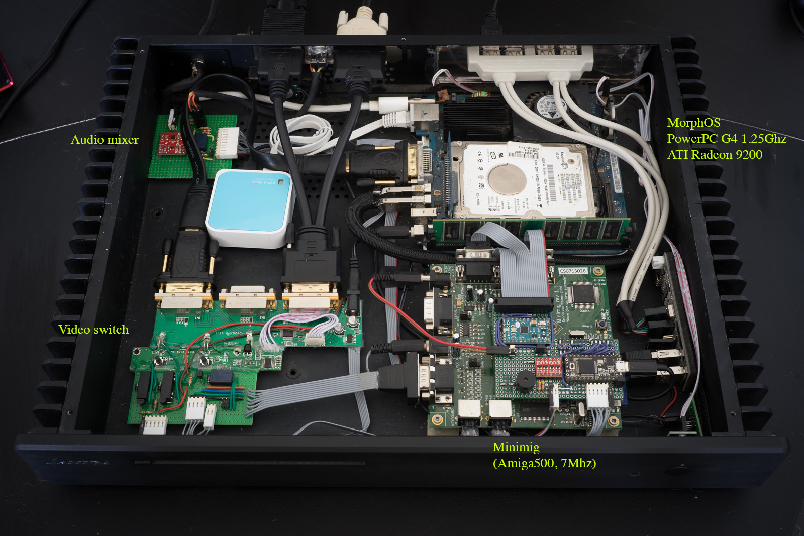
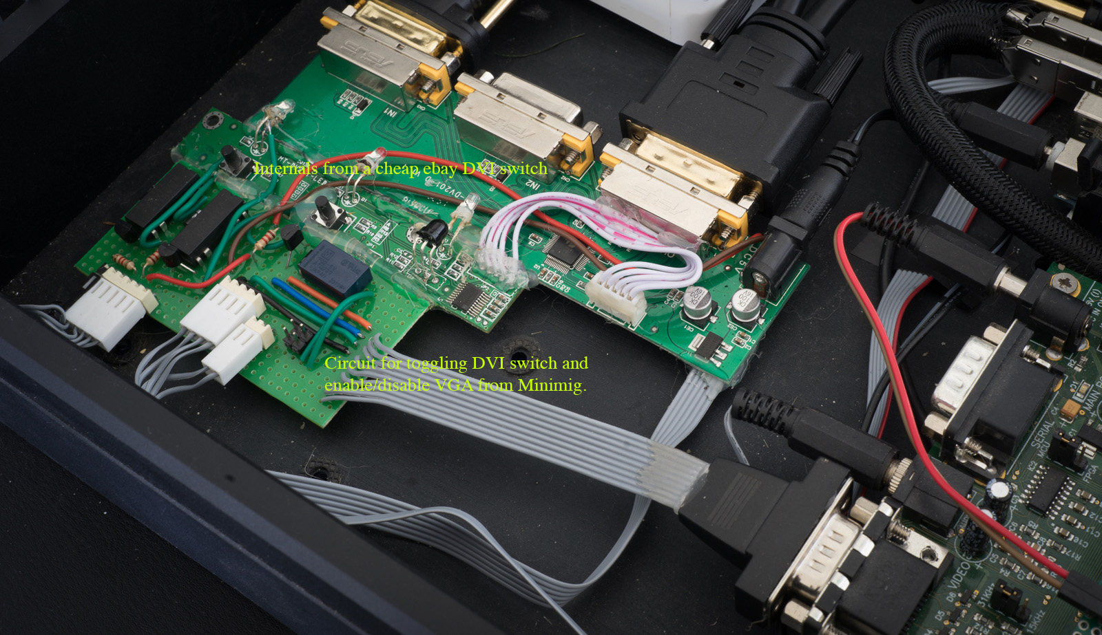
I was not happy with the previous version of the video switch as it required me to use analog output from MorphOS.
The new version is a hacked DVI switch I got for cheap from ebay. Hacked in a way that it outputs DVI-I with either digital signals from MorphOS or analog signals from the Minimig – never both at the same time.
My monitor automatically detects if a cable is “unplugged” or “plugged in” and will switch to the active input.
DSC05118

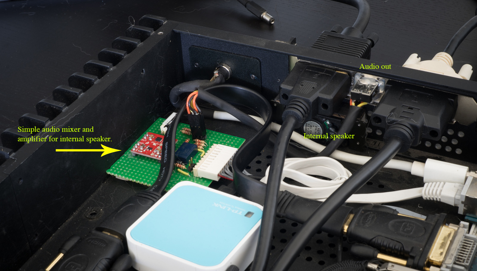
I made a super simple audio mixer for mixing the MorphOS and Minimig audio.
MorphOS audio is always active. Minimig audio is only active when it is running and active (it cuts out if you “alt-tab” to the desktop, or shut down).
There’s also an internal speaker.

DSC05119


Overall I am super happy with the result. It does what I set out to do, make the Minimig feel invisible and completely integrated with MorphOS.
Of course, the sane approach would be to just use UAE instead but this has always been an excuse for me to learn more about electronics and micro controllers.

Random ideas for future improvements could include:

- Send mouse,keyboard and joystick directly to the FPGA over SPI, removing the need for the second micro controller and cable.
- Send picture from Minimig back to MorphOS (over ethernet?) so it can be displayed in a window.
- Make a single card that does all the things (Minimig/MIST, video switch, audio mixer).
- Perhaps with a Sam460 one could skip a microcontroller entierly and just drive it directly from the computer – it has an FPGA and plenty of IO pins directly on the motherboard. Although I doubt I would ever figure out how to access it from MorphOS :(

I don’t have any plans of making a product out of this, so for now I will just enjoy some old classic games, and upgrade to MorphOS 3.9 – I am apparently still on 3.7 :)

DSC05126


Internal speaker

Even though the sound quality is never really that good, I find internal speakers very handy for times when you can’t be bothered connecting up real speakers.
The Mac mini which is donating parts to this project had a speaker so I am experimenting with a tiny low voltage amplifier to drive it.

Here is one built around an LM386N. It’s driven by 5V and I am happy with the volume and quality for what it is.
The small circuit on the left is for getting 5V out of the 18.5V power brick.

internal_speaker


Outputs

Output board is getting close to being finished. It will go in the single PCI slot of the computer chassis and provide audio+video output.

A bit simplified, it is based an a no-name KVM switch that has been butchered, modified and fixed to a PCI backplate.
It’s a good thing it goes inside of the case.. it won’t win any beauty contests that’s for sure!

output board

  • VGA
    - Switchable between PPC / 68K
    - Controlled by software, or using the hardware switch on back
  • Audio line out
    - Mixed audio from PPC + 68K
    - Enables internal speaker when no external plug is connected (small amp+speaker setup yet to be built)
  • 2x USB
    - Connected to PPC
  • Misc
    - 10 pins for connecting to interface board (4pins used)


Chassis

After having spent a lot of time hunting for a nice chassis for the computer I finally found the perfect one for me.

It is a Streacom FC5OD desktop model:

I really like the looks of it, and size wise it suits really well for hosting the powerpc + minimig + other stuff.

chassis chassis2


The chassis has arrived and it is a thing of beauty!

I have not yet started to put any hardware inside of it as it is much easier to have the boards loose on the work table for now. Test fittings show that it should work out really well once I’ve drilled out mounting holes for the mainboards etc.

Also waiting for a 44pin HDD cable from Amigakit so that I can relocate HDD. The mac motherboard is going to be mounted “bare” which means that the original mount for the HDD is not going to be available.

I took the opportunity to order a black background boing-ball case badge as well. I may or may not use it.


Hello world!

First post, and a recap of what has been done so far.

Prototype interface board has been built. It is based around an Arduino compatible Teensy++ development board which contains a AT90USB1286 microcontroller.

The main reason why I went for the Teensy instead of any other Arduino compatible board was the transfer rate of the USB compared to the real Arduino boards (benchmark).

There is a PIC processor on the Minimig which acts as an IO controller. This is convenient since I could just remove it and use the socket as an input for my board. The PIC processor itself was relocated to sit on the interface board instead.

Here it is all soldered up:

interface_board_1

And connected in the PIC socket of the Minimig:

interface_board_2

The interface board is the glue which binds the Minimig together with the PowerPC. I can talk to it from MorphOS over USB, and it in turn can control the Minimig and the VGA switcher hardware.

So far I can power the Minimig on and off, reset it, and feed it with mouse/keyboard/gamepad input coming from the MorphOS side. It can also control a VGA switch to switch between displaying MorphOS and the Minimig on my monitor.

A video of the thing running:

https://www.youtube.com/watch?v=PABMGhbiElY


Next up on the software side is to control floppy disk mount/unmount and in the long run be able to either deploy floppy images to the Minimig SD card and/or “stream” floppy disk content from MorphOS to the Minimig.

There is no risk getting bored with the software side. I get to do MorphOS coding, AVR firmware coding and PIC firmware coding. (In theory I should be able to get rid of the PIC processor and just use the Teensy – to be looked into later)

Hardware is done on prototype board. It would be cool to make proper PCBs when everything is fully finalized but that is still far in the future.